Teardown of the Freestyle Libre 2 Continuous Glucose Monitor
Published December 18, 2023
Hello! Recently I wore a Freestyle Libre 2 continuous glucose monitor for two weeks. They're sold over-the-counter in France for about 40 Euros a pop, and I was curious about what my glucose data could tell me about my other bodily functions.
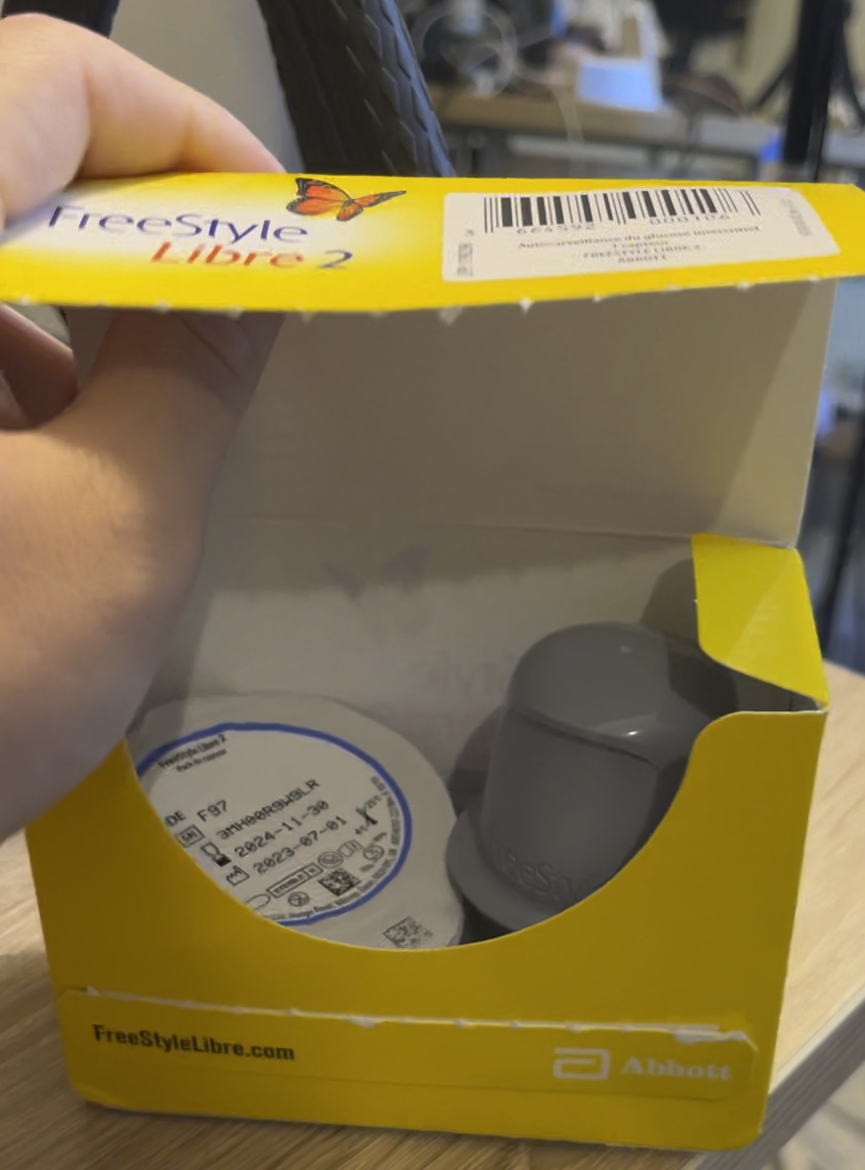
Here's the open box. The monitor + injector comes in two pieces. The bottom sealed cup has the monitor in it, here you can see the little triangular piece that has the needle.
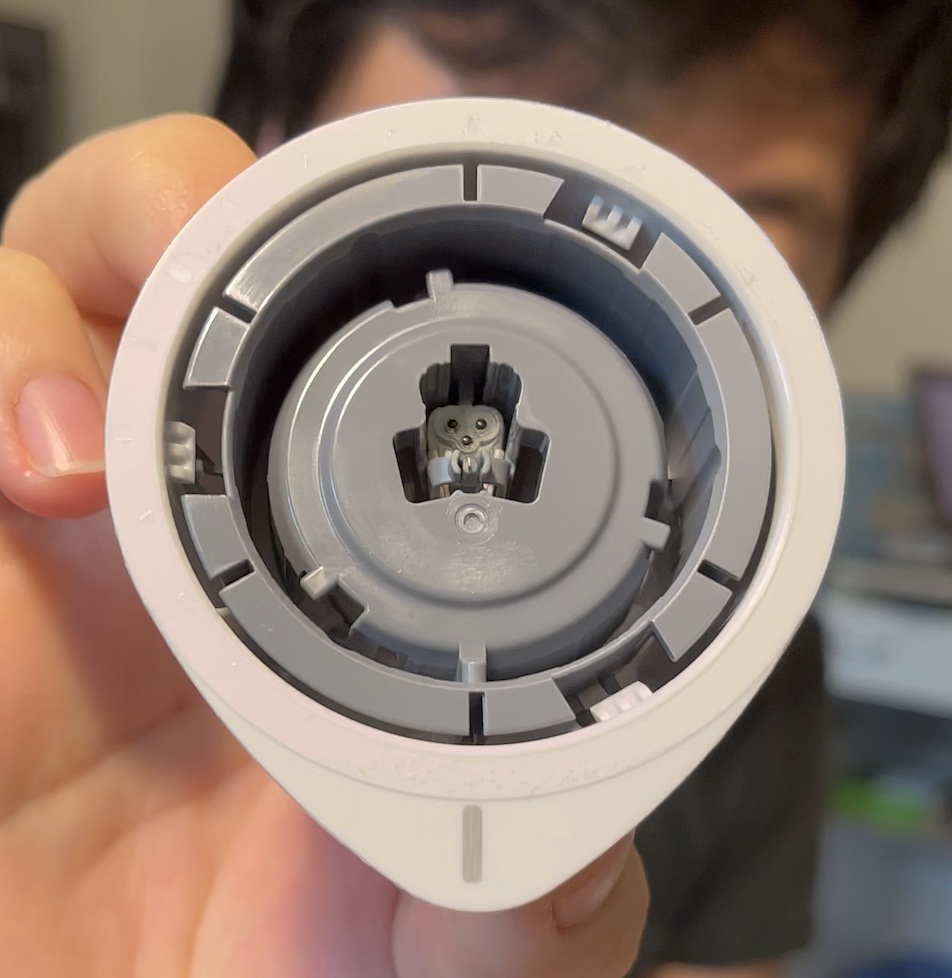
You click the top grey part into the bottom cup and the monitor gets loaded into the applicator, needle-side out.
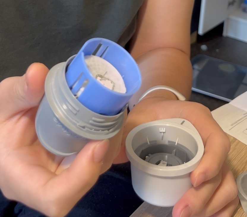
This gets injected into your arm or hip somewhere, where it connects to an app via Bluetooth.
After about two weeks, my app said the monitor's two week lifespan had ended, and that I should purchase another one. Since I didn't notice any noticeable correlation between my blood glucose peaks and bodily functions (brain fog, tiredness, energy, etc.), I didn't opt to get another one.
I kept the sensor around because I wanted to know how it worked, and finally got around to deconstructing it
Teardown
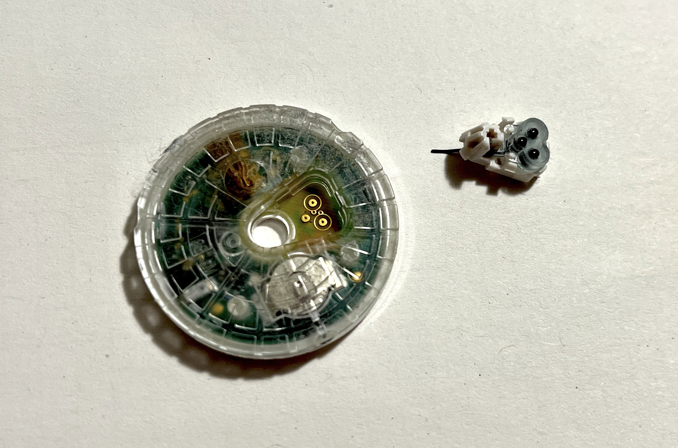
First I removed the needle assembly, it has these three black squishy contacts that the needle feeds into. These touch the three golden circular pads on the Libre Freestyle 2
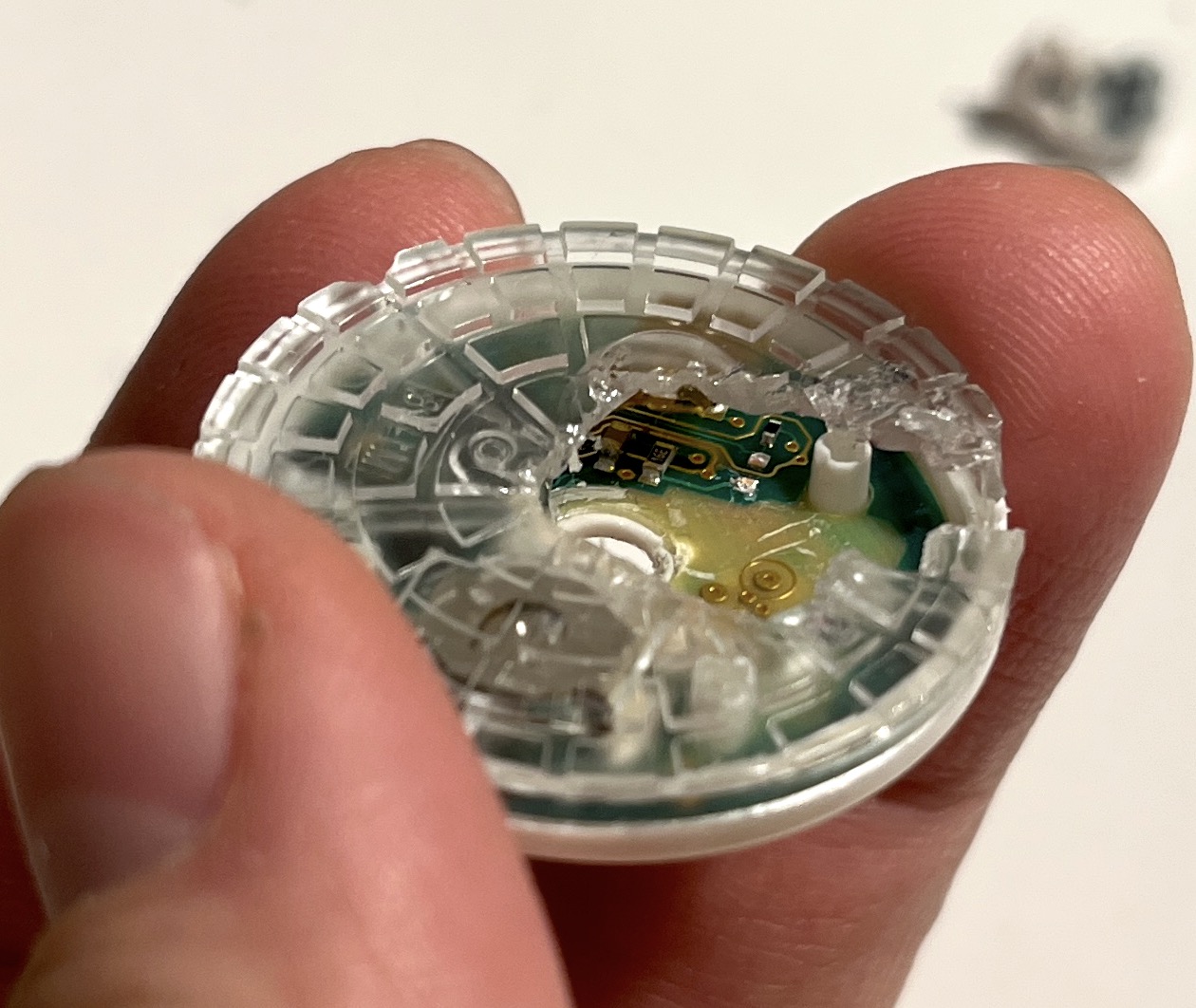
From the top, it looks like the two shells are held together by a plastic rod on one going into a plastic hole on the other, and the fit is quite snug. I started using pliers to tear into the plastic housing and that worked nicely.
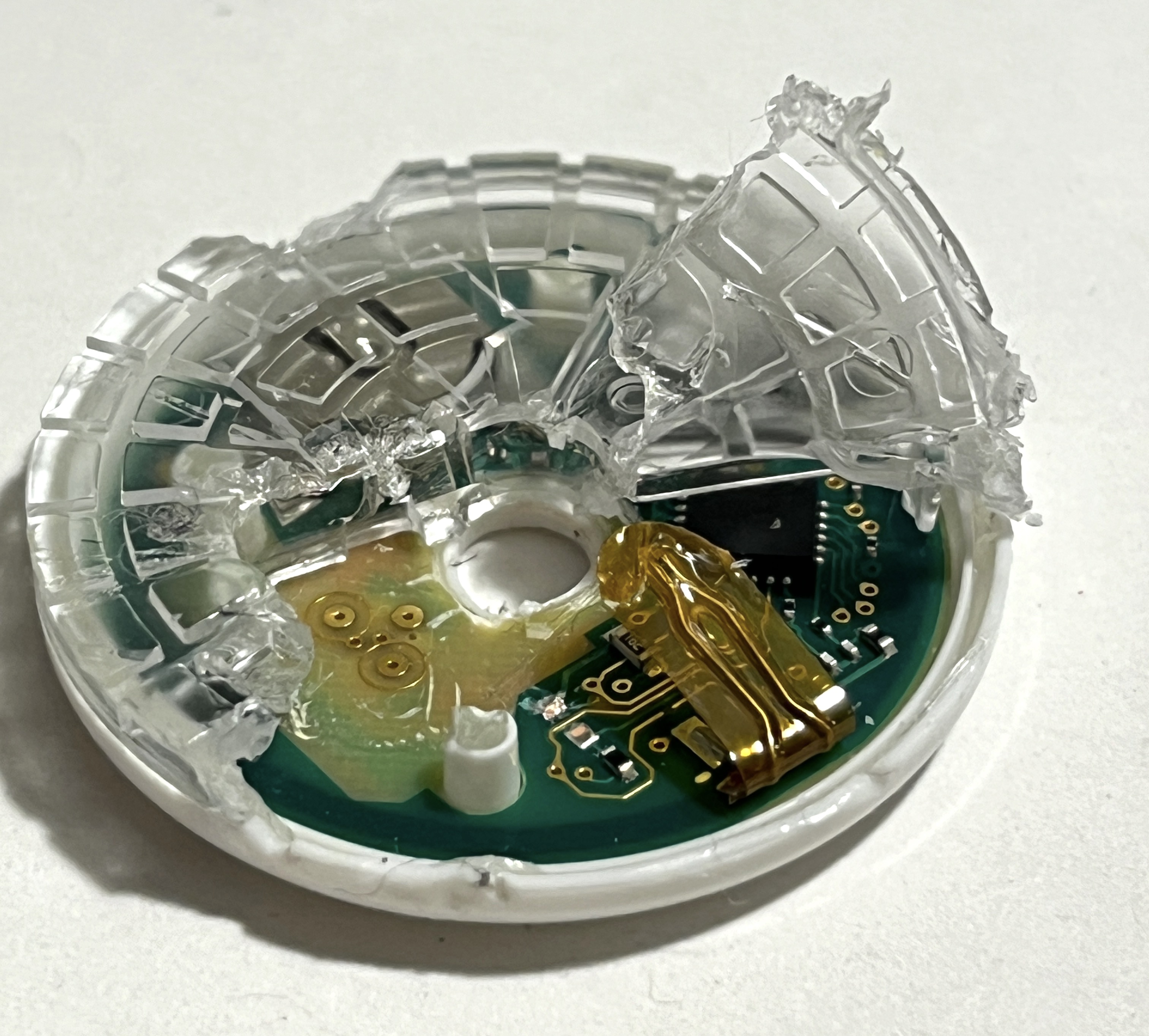
One of the first things I encountered was this taped sensor. I didn't have my multimeter on me to check, but it looks a bit like a thermal resistor used to roughly estimate temperature changes. Maybe for skin detection?
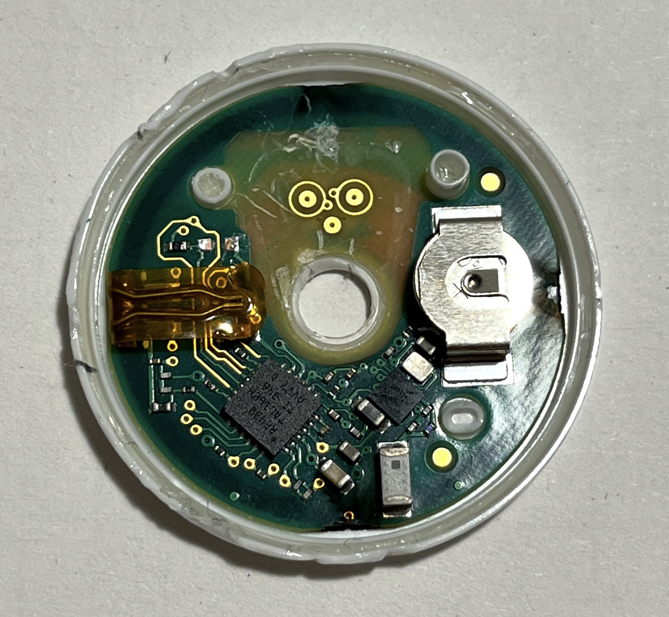
After removing all the plastic, we can take a nice gander. The main microcontroller has an RF430 marking, looks like the TI RF430 NFC chip which also has an ADC.
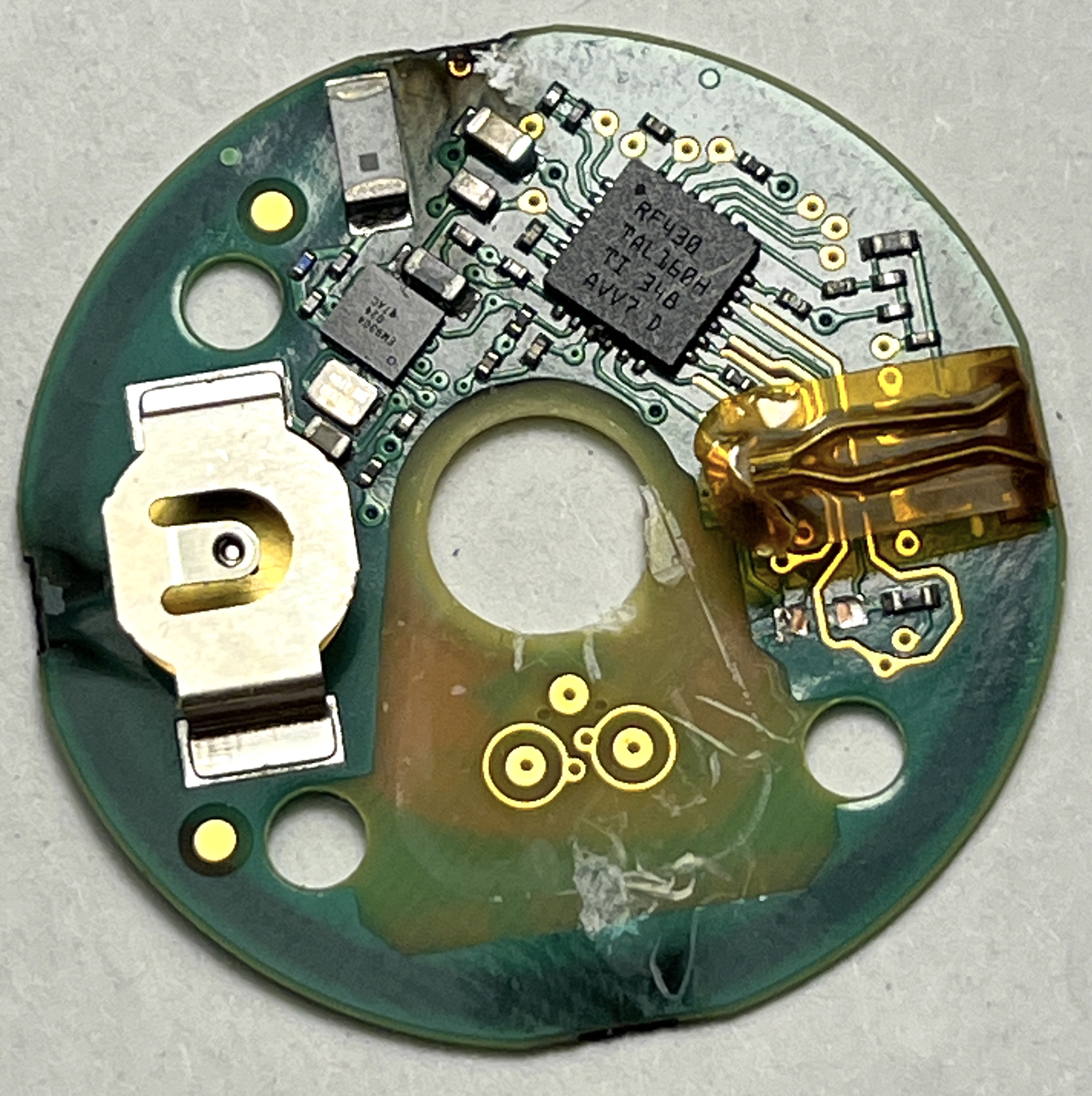

I heard that the older Freestyle Libres used NFC only, requiring a user to tap their phone to the device to get readings out periodically. But mine had bluetooth, so what's doing that? There's also a PCB antenna at the top for wireless communication, furthering my suspicions that NFC is not the only thing here...
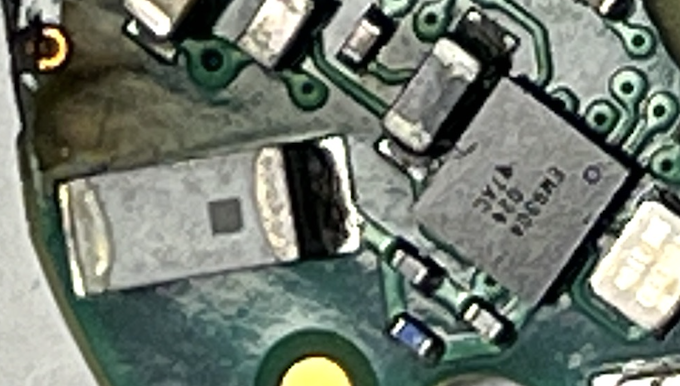
I'd venture a guess it's this chip on the the right, but I can't quite make out the letters in this picture. The antenna + clock right next to it seem to imply this IC does some thinking, and it may be responsible for the Bluetooth.
Guard Ring
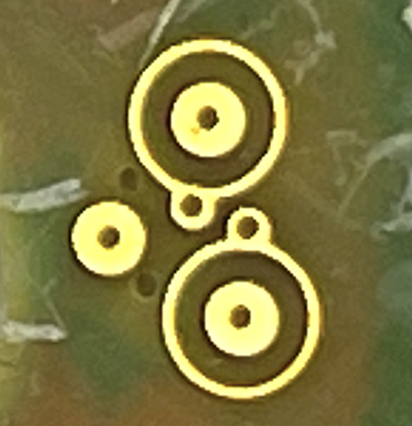
These crop circle-looking contacts for the needle are also interesting. I think this is the first time I've seen guard rings actually put to use in a circuit. They continue on the back
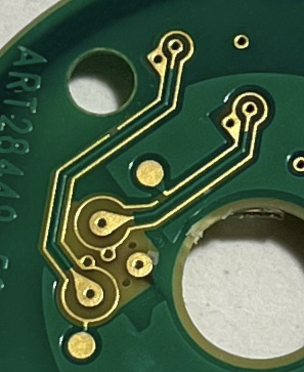
I'm no expert, but I think guard rings are placed around the high input impedance inputs of an op-amp or ADC to prevent leakage current from affecting the measurement. Because the input signal can also have a high impedance, the leakage current across the PCB soldermask can significantly alter the signal. The guard ring is a grounded circle which attenuates any leakage current by shorting it out before it can get to the signal path. I'm guessing the signal that this CGM looks at is quite small or sensitive to noise.
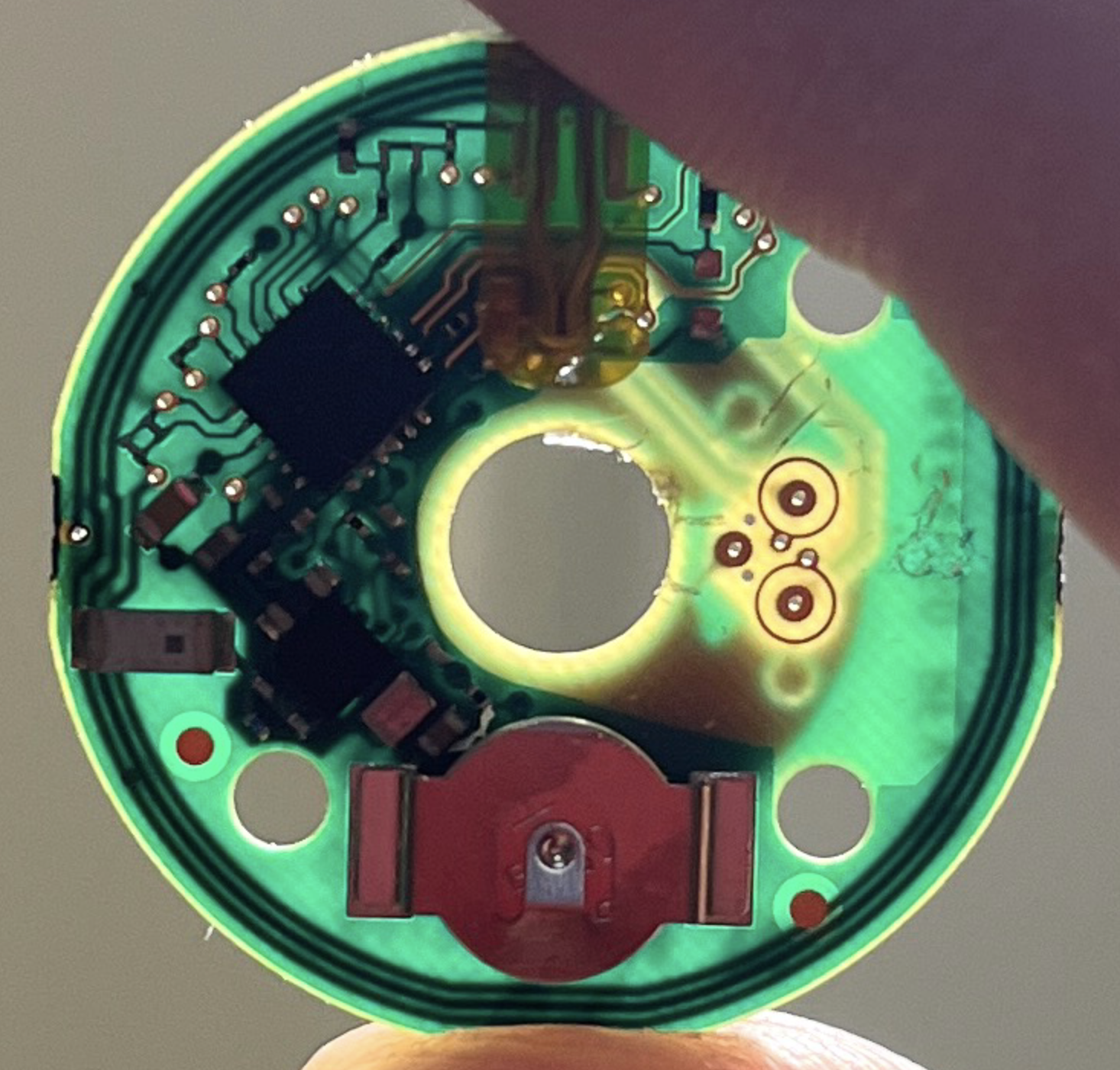
Here's another picture of the CGM against the light. You can see both the guard inputs and some of the inputs from the main NFC chip. There's also a big copper trace that loops the whole board a few times - this looks like the coil that the NFC chip uses.
I also wanted to measure the battery voltage at the end of the two weeks to see if the battery had really run out, or if this was some kind of planned obselescence play. Unfortunately I waited too long to check.
Also, I believed that the needle had some kind of special liquid which turned the glucose level into a voltage. This doesn't seem to be the case, at least I couldn't see anything that would imply some "glucose electrifying liquid" that gets used up. There is a weird little loop of wire though on the needle, not sure what that is...
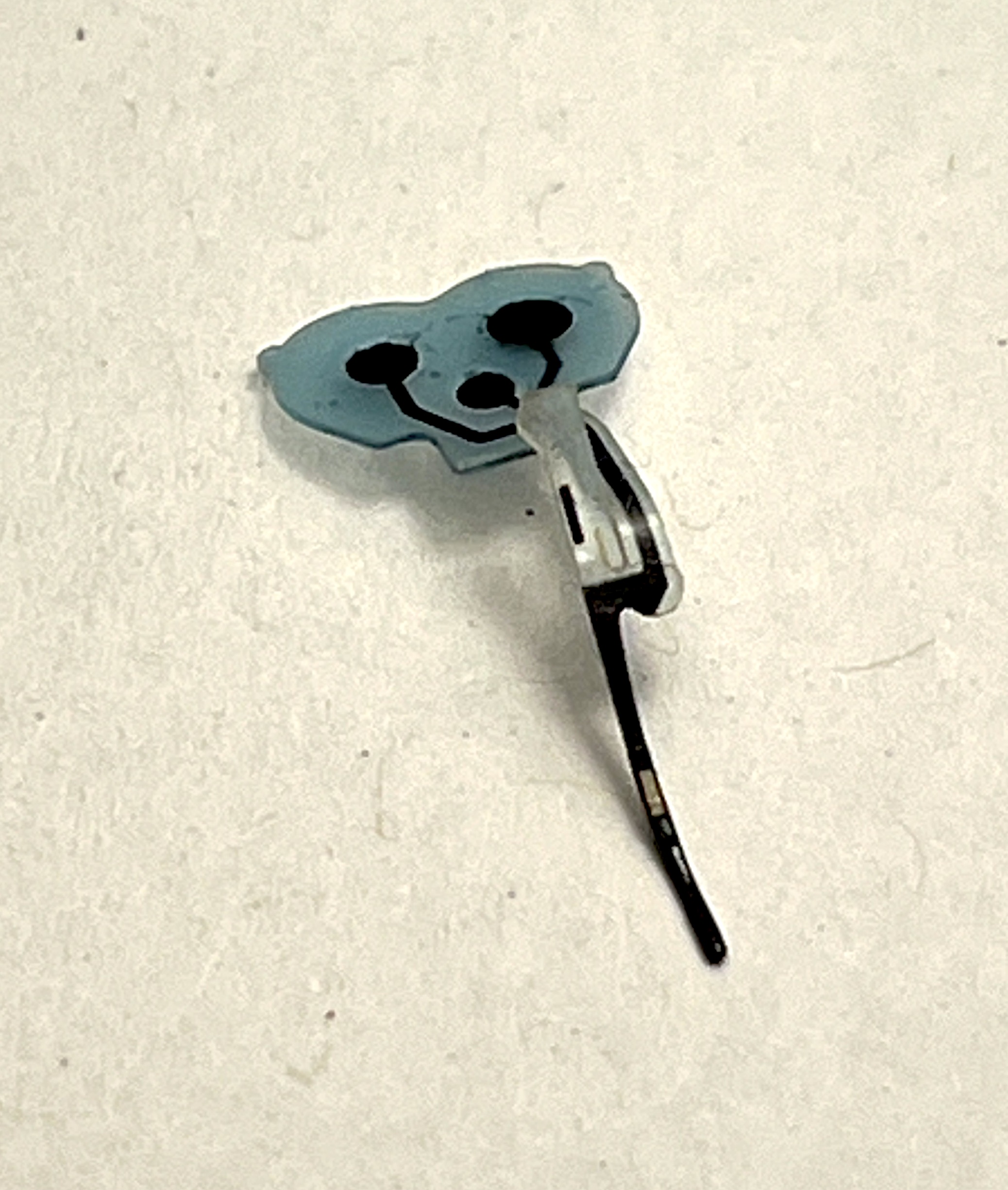
The little black dots here have tiny holes on the surface, and feel quite rubbery. I wonder if my blood actually traverses the tube and goes up to the PCB, or if some other mojo happens lower down in the needle?
Anyway, that's all for now. I will be posting the results I got from the glucose data at some later time. Cya!