Using flex PCB as electrode mount
Published February 3, 2026
Recently I built a wearable EKG circuit with Lucia for a fun party device that visualizes your heart rate.
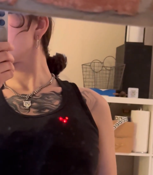
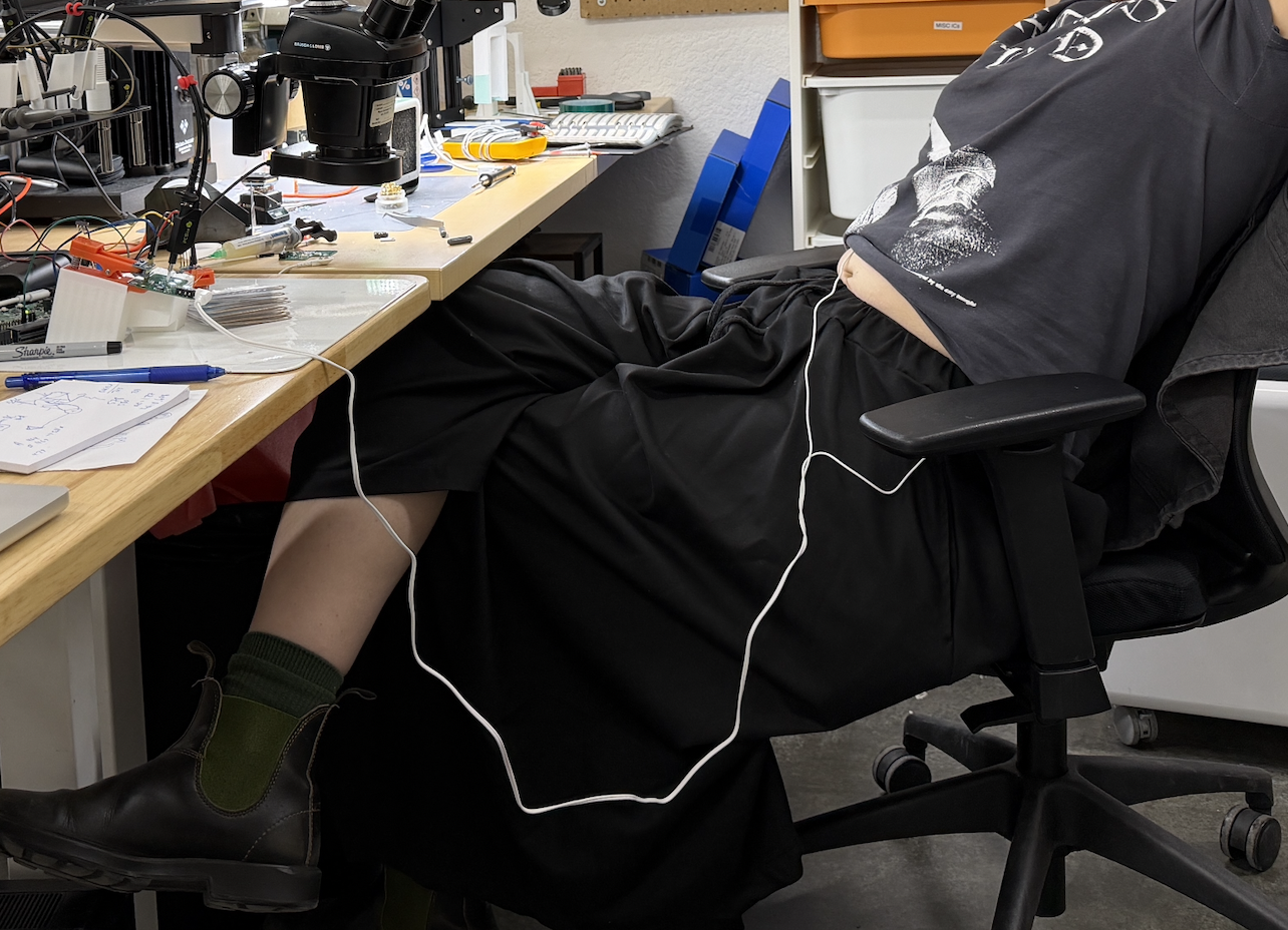
The most clunky part of any biosensing project is coupling the human to the circuit, and this was no different. We had to get EKG gel electrodes, corresponding snap electrode cables, and then connect them to the person in question. This is annoying because the electrodes are disposable, the wires are too long and windy, and the connection to the board is bulky because the EKG electrodes normally go off-body to get digitized.
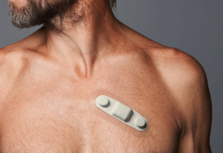
It would be much nicer if the EKG was an all-in-one piece that sits across the heart and captured the same signal. A worn EKG like this exists already for monitoring people over 1-2 days, but it isn't fun or hackable or attainable by normal people, so I was looking for alternatives.
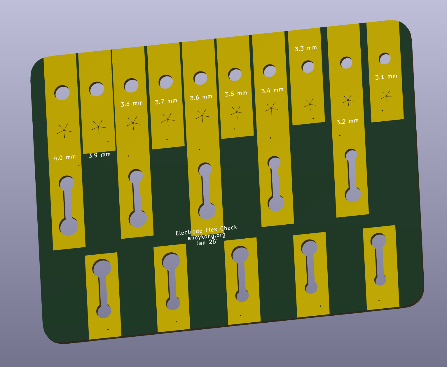
One such method used flex PCBs as the "snap", using the flexibility of the FPC material to ensure good contact with an electrode. I could think of many ways to do this coupling but I had two problems: I wasn't sure how big the electrodes were (no calipers) and I could think of 3+ ways to shape the electrode-mounting hole on the FPC itself. I started by modeling out the different geometries for this (simple hole, star-shaped hole, and keyhole) in 10 different sizes spanning 3-4mm (I knew we had a 3.5mm snap electrode, I just wasn't sure which part was 3.5mm). I got this on flex, and just for fun I ordered it on JLC's clear PCB.
They emailed me immediately asking about soldermask, and since I wanted the gold to be exposed for good contact, I told them to remove all of it. As it turns out, the base material of the clear FPC is clear (and slightly pink?), but the surface finish is not smooth enough to see through it without soldermask. You can approximate the soldermask with a piece of clear tape on both sides.
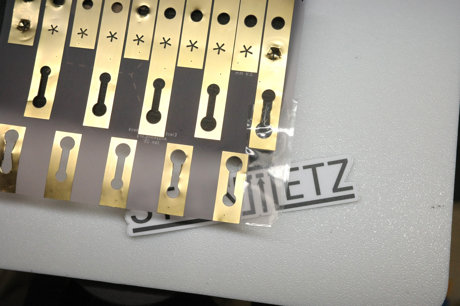
As for the electrodes, it turns out just pretending the buckle was perfectly 3.5mm is a decent strategy. The simple hole performed ok, the star-hole had a bit too much material in the middle, and the keyhole worked just as well as the simple hole (but needed smaller sizes).
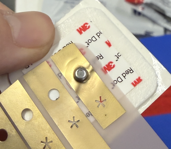
It's easy to say in hindsight, but the simple holes used the flexibility of the metal, which deforms and does not snap back. This meant repeated use of a single hole meant it stopped making good contact (though it still held on to the electrode well enough).
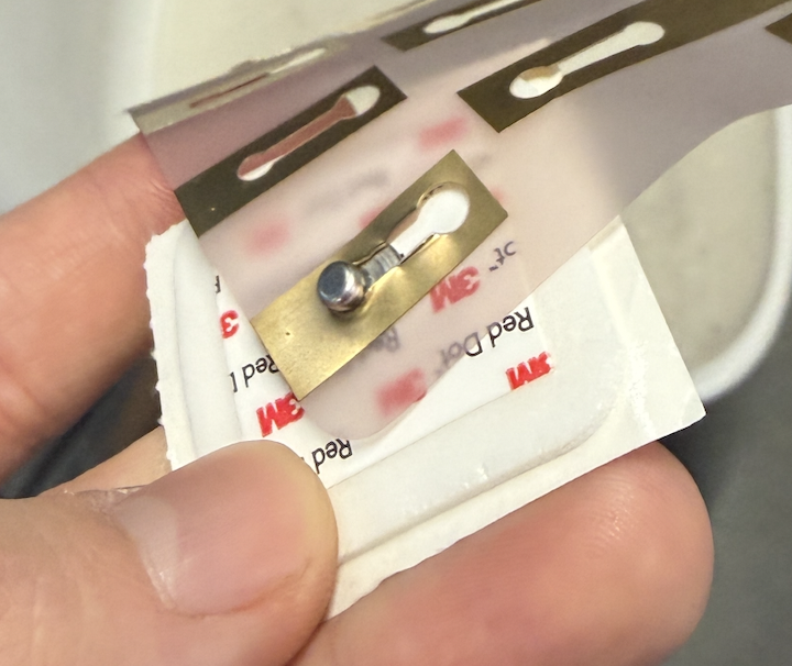
The keyhole intermediate channel was 2mm, and held much more consistently across uses. I think this is because it relied on the flexibility of the underlying substrate, or on the flexing as opposed to the deformation of the thin metal layer. In the future we'll go with the too-thin channel, and I think the electrode clips and EKG circuit will be able to all fit on the same circuit.